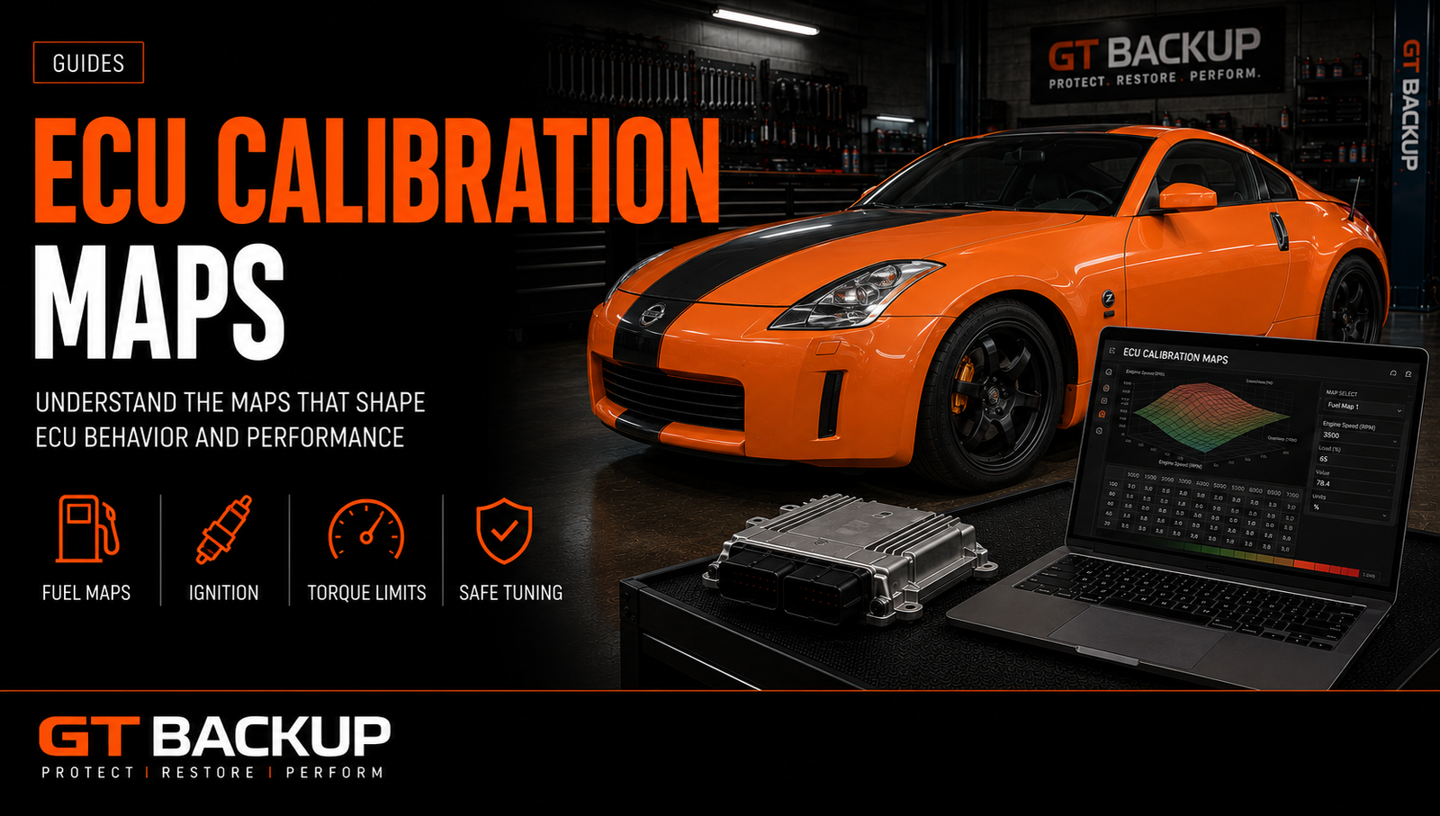
ECU calibration maps are not independent “power tables”. They form a connected control strategy that converts driver demand into torque while managing air, fuel, ignition, boost, emissions, temperatures and component protection.
For example, a map is usually a table or curve indexed by variables such as engine speed, load, air mass, pressure or temperature. Understanding the main map families explains why safe calibration is not achieved by increasing a few values. Requests, limiters, models, actuators and monitors must remain coherent.
What is an ECU calibration map?
Control-unit software contains program code and calibration data. The code performs calculations and logic; calibration values define targets, limits, conversions and responses for a particular engine and vehicle.
A two-dimensional curve might vary a limit with engine speed. A three-dimensional table might use speed on one axis and load on another, with the cells containing ignition angle, fuel quantity or pressure target. Some values are switches, constants, correction factors or multi-dimensional structures rather than visible “maps”.
ECU calibration maps: axes, units and interpolation
First, correct map interpretation starts with axes and units. A table is meaningless if engine speed, load, pressure, temperature or torque scaling is wrong.
Moreover, the ECU usually interpolates between breakpoints rather than jumping directly from one cell to the next. Smooth, physically sensible surfaces matter because abrupt gradients can create unstable commands or unexpected transitions. Calibration software may display raw integers, converted engineering units, 2D curves, 3D surfaces or hexadecimal data.
Modern ECUs are often torque-based
Many modern engine controllers organise decisions around torque. The accelerator pedal creates a driver request, but the final permitted torque passes through multiple constraints:
- driver-demand maps;
- engine and gearbox torque limits;
- traction and stability requests;
- temperature and altitude corrections;
- air and fuel availability;
- component protection;
- emissions and diagnostic strategies.
Next, the ECU converts permitted torque into air charge, fuel quantity, ignition, boost, throttle or injection commands. Increasing one limiter without aligning the model can produce intervention, incorrect reported torque or inconsistent transmission behaviour.
Driver-demand maps
For example, driver-demand tables translate pedal position and engine speed into a requested torque or load. They strongly influence pedal feel but do not guarantee the requested output: downstream limits may reduce it.
However, an aggressive pedal map can make a vehicle feel faster at small pedal movement without increasing maximum power. Good calibration preserves controllability in traffic, wet conditions and low gears rather than using sensitivity to imitate performance.
Torque limiters
In addition, torque limiters protect the engine, clutch, gearbox, driveline and thermal system. They may vary by speed, gear, temperature, pressure, altitude or operating mode.
Therefore, a calibration should identify which limiter is active and why. Raising every apparent torque value can damage model consistency and remove legitimate protection. Requested, permitted, indicated and reported torque may each have separate structures.
ECU calibration maps for air charge and boost
Turbocharged engines use targets and control maps for manifold pressure, air mass, wastegate duty or variable-geometry position. Supporting structures may include:
- load or cylinder-charge targets;
- boost-pressure limits;
- turbo speed or pressure-ratio protection;
- air-temperature and altitude correction;
- wastegate or vane pre-control;
- closed-loop controller gains;
- overboost and plausibility diagnostics.
However, more boost target does not necessarily produce more safe airflow. Compressor efficiency, charge temperature, exhaust backpressure and turbo speed matter. Bosch Motorsport’s official ECU datasheet illustrates how torque structure, lambda and knock control operate within one coordinated strategy. Validation compares requested and actual pressure, control duty and temperature rather than trusting the edited table.
Petrol fuelling and ECU calibration maps
Likewise, petrol ECUs may express mixture as lambda, air-fuel ratio, equivalence ratio or fuel mass. Closed-loop operation uses oxygen-sensor feedback around appropriate targets, while high-load enrichment may protect components and manage combustion temperature.
Important structures can include:
- lambda targets by load and speed;
- cold-start and warm-up enrichment;
- injector characterisation and fuel-pressure targets;
- transient fuel compensation;
- component-protection enrichment;
- fuel-trim and adaptation limits.
However, injector scaling is not a substitute for a complete calibration. Incorrect data can distort calculated load, trims, diagnostics and cold operation.
Ignition timing maps
In addition, ignition maps set spark angle according to operating conditions. Base timing is modified by intake temperature, coolant temperature, knock control, fuel quality, cylinder-specific correction and protection strategies.
However, maximum advance is not the goal. Timing should deliver stable torque with appropriate knock margin. A dyno result must be supported by cylinder correction, fuel consistency and repeated hot testing. One clean run in cool conditions does not validate the entire table.
Diesel injection quantity and smoke control
By contrast, diesel calibration often coordinates requested torque, injection quantity, available air and smoke limitation. A smoke limiter may use air mass or calculated charge to restrict fuel when oxygen is insufficient.
Related maps include:
- torque-to-fuel conversion;
- injection-quantity limits;
- air-mass or lambda smoke control;
- rail-pressure targets and limits;
- start of injection;
- duration and injector calibration;
- pilot, main and post-injection strategies.
Consequently, adding duration without understanding pressure, timing and injector flow can raise temperature and soot without proportional torque. Visible smoke is not evidence of a successful map.
Rail-pressure maps
Similarly, common-rail pressure influences atomisation and delivered quantity, but higher pressure increases pump and injector load. Targets must respect hardware, fuel temperature and control authority.
Therefore, requested pressure, actual pressure, control-valve duty and pressure error should be logged. Masking a rail-pressure DTC or raising limits to hide poor tracking is not calibration.
Injection timing and duration
Moreover, diesel combustion depends on when injection starts, how long it lasts and how events are split. Timing affects cylinder pressure, noise, efficiency, exhaust temperature and emissions.
For example, duration tables usually convert desired fuel quantity and pressure into injector opening time. Their units and structure are injector-specific. Editing them blindly can corrupt fuel delivery across the operating range.
Variable valve timing and throttle maps
In addition, petrol and some diesel engines use cam phasing, valve lift, throttle and intake-runner control to manage charge, residual gas, torque and emissions. These systems interact with the torque and air models.
Consequently, a change in cam target can alter airflow, knock tendency, exhaust temperature and turbo response. It requires measurement, not only a visually smooth table.
ECU calibration maps for temperature and component protection
ECUs monitor coolant, oil, intake air, exhaust gas, catalyst and sometimes turbocharger temperature. Protection can reduce torque, enrich mixture, change boost, retard ignition or request cooling.
However, disabling temperature protection to prevent intervention is dangerous. If a protection activates during testing, determine whether the target, hardware or cooling system is outside a sensible range.
Knock control and fuel quality
Knock control detects abnormal combustion and adjusts timing within calibrated authority. It is a safety and adaptation system, not permission to run an unsuitable base calibration.
Fuel octane, charge temperature, deposits and cylinder variation influence knock. A calibration specified for one fuel must not be assumed safe on another. Preserve functional detection, correction and diagnostic limits.
Diagnostics and plausibility maps
OBD monitors compare commands, sensors and modelled behaviour. Thresholds identify boost deviation, fuel-pressure error, airflow plausibility, misfire, catalyst efficiency and many other faults.
However, changing DTC thresholds to hide an error removes evidence without fixing the cause. A sound performance calibration retains honest monitoring unless an approved change in hardware and software strategy genuinely requires documented recalibration.

Why one map never tells the complete story
Suppose a calibrator raises boost. The torque request, load target and pressure limit may permit it, but air-temperature correction, turbo protection or gearbox torque limits may still intervene. Additional airflow may require different fuel and ignition targets. Reported torque may need to remain consistent with transmission communication.
The correct question is not “Which boost map do I change?” but “Which control chain requests, limits, delivers, monitors and protects this operating point?”
Map packs, DAMOS and A2L data
Definition files can provide labels, addresses, axes, units and descriptions. Their quality and compatibility are critical. A definition for a similar software version may point to the wrong location or scaling.
Always verify definitions against the exact binary, software identifiers, code references, patterns and expected physical behaviour. A label is helpful evidence, not automatic proof.
Checksums and file integrity
Checksums help the ECU detect corrupted or altered memory regions. After calibration changes, applicable checksums must be corrected using a verified method.
A correct checksum proves neither map identification nor safe values. It only addresses integrity. Likewise, tool software claiming automatic correction does not remove the need to keep the original file and verify the written result.
Professional workflow for ECU calibration maps
- Identify: confirm VIN, engine, transmission, ECU hardware and software.
- Baseline: scan DTCs, inspect the vehicle and record standard performance data.
- Back up: save the exact original read and label read method and tool.
- Define targets: choose realistic output for hardware, fuel and intended use.
- Map the control chain: identify requests, limiters, conversions, actuators and protections.
- Edit coherently: maintain smooth surfaces and consistent units.
- Verify integrity: compare changes and correct checksums.
- Write safely: use stable power and the correct protocol.
- Log: compare requested and actual torque, air, fuel, pressure, ignition and temperatures.
- Validate: test repeated hot operation, transient response, DTCs and protections.
- Document: keep original, modified file, logs and calibration notes.
How to recognise poor map editing
- large rectangular percentage changes with no physical rationale;
- abrupt steps or broken table gradients;
- every limiter raised to the same extreme value;
- diagnostics and protections disabled to hide intervention;
- claimed targets unsupported by logs;
- incorrect axes, scaling or software definition;
- no exact original backup;
- no baseline scan or post-write validation.
Frequently asked questions about ECU calibration maps
How many maps are inside an ECU?
There is no useful universal number. Controllers contain many tables, curves, constants, switches and corrections; only a subset may be relevant to one calibration goal.
Can every map be displayed in 3D?
Many tables can, but 3D is only a view. Correct axes, units and function matter more than appearance.
Is WinOLS or another editor enough to tune safely?
An editor helps locate and modify data. It does not supply engine knowledge, correct definitions, vehicle diagnosis or validation.
Can a percentage increase create a Stage 1?
Not reliably. Different map families use different units and physical limits. Coherent targets and logged validation are required.
What information should be supplied with a file?
Provide VIN, engine and gearbox, ECU references, exact read, tool and mode, fuel, hardware changes, diagnostic scan, intended output and vehicle use.
ECU calibration maps: the correct conclusion
Calibration is a coordinated system. Driver request, torque, air charge, fuel, ignition, boost, temperatures, protections and diagnostics must agree across the full operating range. A colourful 3D surface is not a tune; validated control behaviour is.
For professional analysis, contact GTBackup with the original file and identification, read our ECU file types guide, or review file-service pricing. Accurate definitions, traceable changes and measured validation turn ECU maps into a reliable calibration.